

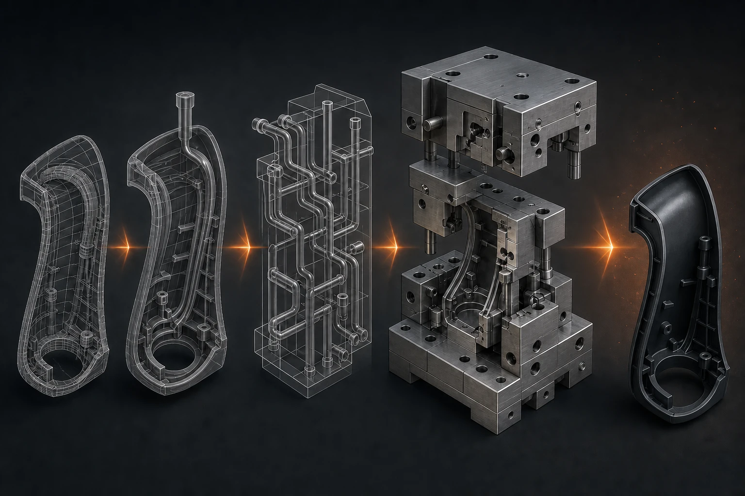
A production mould should be treated as a manufacturing system, not a machining purchase. Good toolmaking connects DFM, filling and cooling analysis, detailed design, machining, fitting, trials, correction and long-term maintenance.
For OEM procurement, product engineering and supplier-quality teams, the strongest sourcing decision comes from linking the part requirement to a practical manufacturing and validation plan. This guide explains what to specify, what to verify and what to include in the RFQ.
The essentials
- Freeze inputs and open points before tool design.
- Design the mould around the target machine and production volume.
- Use trials to learn and correct, not merely to produce samples.
- Agree handover, spares, maintenance and change control before acceptance.
Controlled inputs and the DFM review scope
Start with controlled 3D data, drawing, resin, volume and target machine. DFM should address wall sections, draft, undercuts, ribs, bosses and appearance.
Mouldflow and cooling review
Mouldflow can inform filling, pressure, weld-line and air-trap decisions. Cooling review should target balanced heat removal and accessible circuits.
Cavitation, runner and gate decisions
Cavitation follows demand, part risk, tool size and commercial strategy. The runner and gate concept affects material use, vestige and process balance.
What to compare
| Area | Evidence to request |
|---|---|
| Inputs | CAD, drawing, resin, volume and target machine |
| Engineering | DFM, filling, cooling, venting and steel-safe plan |
| Manufacture | Machining, EDM, fitting and spotting route |
| Trials | Recorded settings, samples, dimensions and corrections |
| Handover | Documents, spares, maintenance and acceptance |
Venting and steel-safe correction strategy
Venting should be designed around likely end-of-fill locations. Steel-safe strategy creates a controlled route for dimensional correction.
Tool steel, surface treatment and machining routes
Tool steel and surface treatment should match resin, volume and maintenance needs. CNC, EDM, wire cutting, grinding and fitting each serve different features.
Die spotting and recorded production trials
Spotting verifies shut-offs, parting lines and contact before trials. Trials should record machine, material condition, settings, cavity and results.
Measured correction and acceptance planning
Dimensional correction should use measured, conditioned parts. The acceptance plan should include samples, reports and agreed functional checks.
Tool handover, spares and maintenance history
Handover needs drawings, spares, maintenance instructions and tool history. The RFQ should include machine interfaces, tool standard and acceptance stages.
Questions worth asking before nomination
- Which input assumptions could change the tool, process route or quoted price?
- Which characteristics are controlled by process settings, and which require inspection of every part or lot?
- What will be measured during trials, and who approves the result?
- How are material, cavity, machine, assembly and inspection records connected?
- What happens when a drawing, material or demand profile changes after nomination?
Handover needs drawings, spares, maintenance instructions and tool history. The RFQ should include machine interfaces, tool standard and acceptance stages. These questions turn a capability discussion into a clear technical and commercial responsibility map.
How Premier supports this work
Premier’s tool-room capabilities cover CAD design, mould-flow and cooling analysis, CNC milling, CNC EDM, die spotting, plastic tooling and production trials. This allows tooling decisions to remain connected to the moulding process that follows.
Premier’s engineering, tooling, manufacturing and quality teams can review the requirement against the drawing, material, production volume and agreed validation plan. The useful starting point is the component data, not a generic capability question.
What to include in the RFQ
- Controlled 3D CAD and the latest drawing revision.
- Component function, mating interfaces and critical characteristics.
- Exact material grade, or the service conditions if material selection is open.
- Annual volume, peak demand, programme timing and target production location.
- Existing tooling status, target machine interfaces and ownership requirements.
- Appearance zones, packaging expectations and traceability requirements.
- Applicable customer specifications, standards and validation methods.
- Samples, mating parts and previous failure information where available.
A complete input pack shortens feasibility review and makes quotations easier to compare. If a value is not yet fixed, identify it as an open engineering decision and provide the condition it must satisfy.
Start a technical review
Send the drawing, material requirement, expected volume and validation plan through Premier’s manufacturing enquiry page. The relevant engineering, tooling, manufacturing and quality teams can then review the part and respond against the actual scope.
Related capabilities
Technical references
- Customer drawing, material specification and applicable validation standards should remain the controlling technical references.