
Product Engineering and Reverse Engineering
Turn an existing part into a production-ready design.
Reverse engineering, design support and dimensional capture connect customer surfaces to a manufacturable component definition.
What we can support
Engineering work that resolves the component before tooling.
Geometry capture, product definition and tooling handoff are reviewed as one connected engineering sequence.
Capture
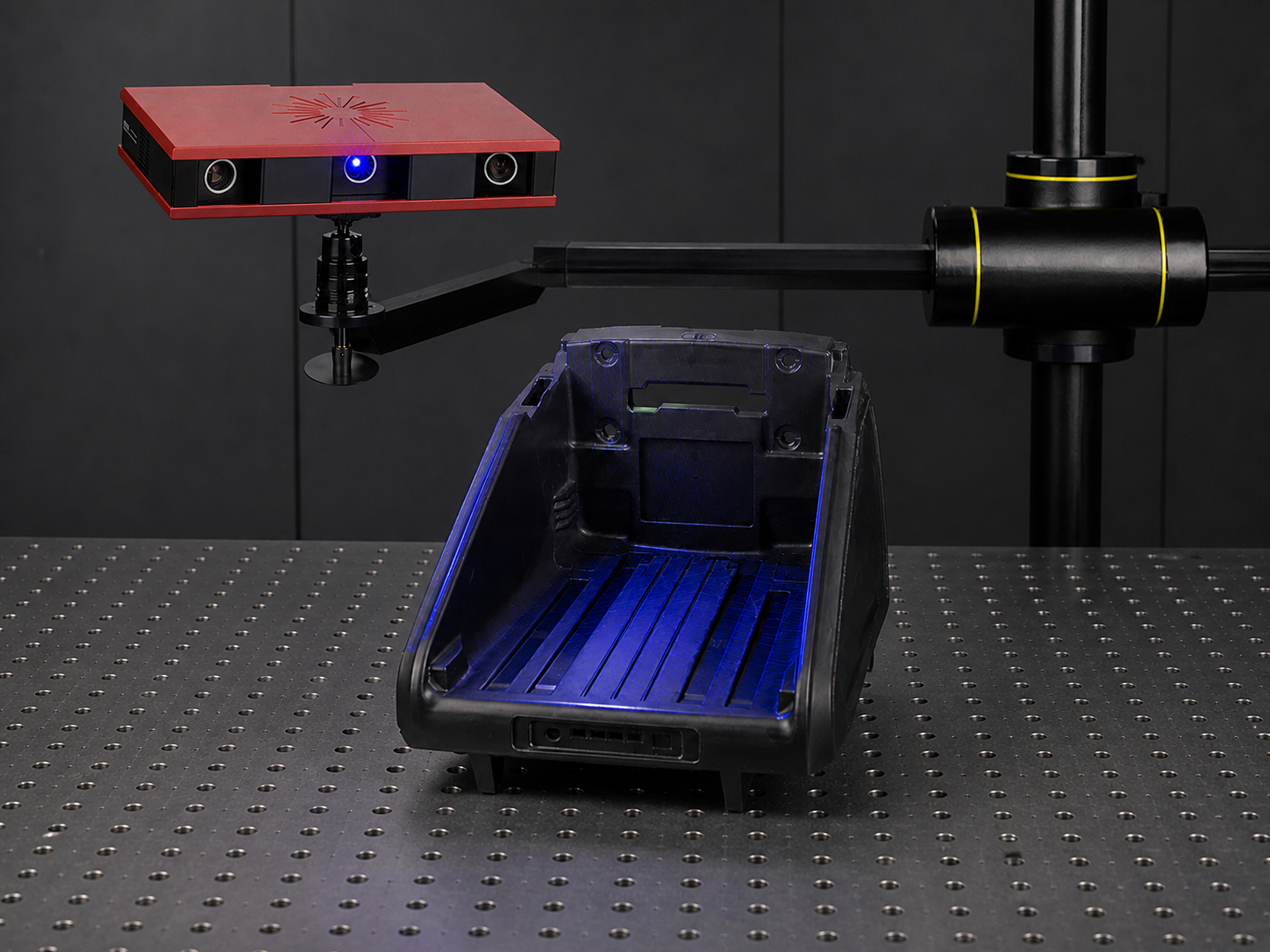
Reverse engineering
Physical references are scanned, measured and translated into controlled geometry for development review.
Review validation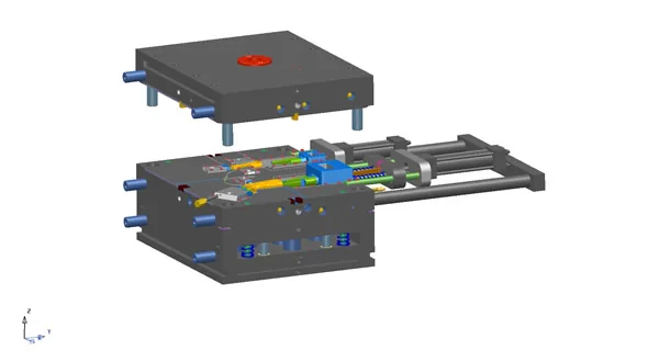
Definition
Product design support
Customer surfaces and functional requirements are developed into mouldable part definitions.
Review tooling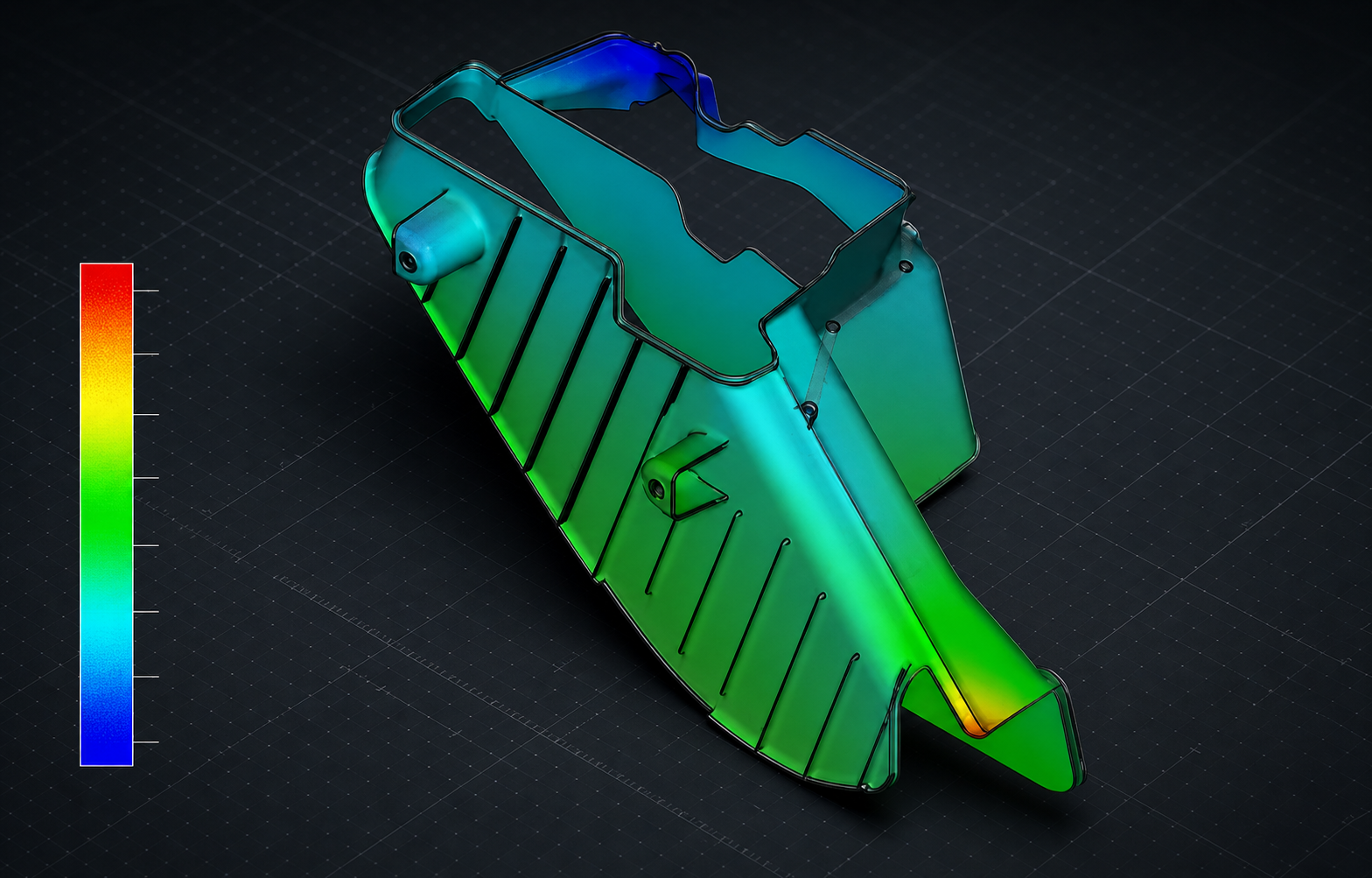
Release
Tooling handoff
Approved geometry moves into mould-flow, cooling analysis and tool design through one engineering chain.
Review toolingHow the work moves
Reference geometry becomes controlled production intent.
- 01
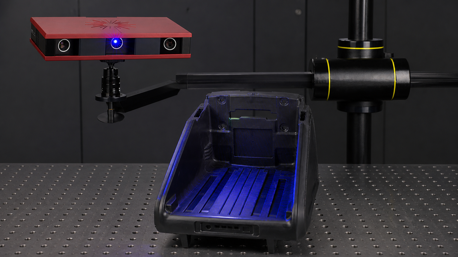
The engineering sequence begins with a defined functional requirement. Requirement definition
Clarify function, interfaces, material intent and the evidence required for release.
Discuss the programme - 02
Geometry capture
Scan or measure the part and prepare an accurate production design.
- 03
Engineering resolves component definition before the tooling release. Product definition
Develop the surfaces, interfaces and component features required for moulding.
- 04
Analysis links component intent to the practical tooling and process route. Manufacturability review
Review mould flow, cooling, split strategy and process constraints as applicable.
Review tooling - 05
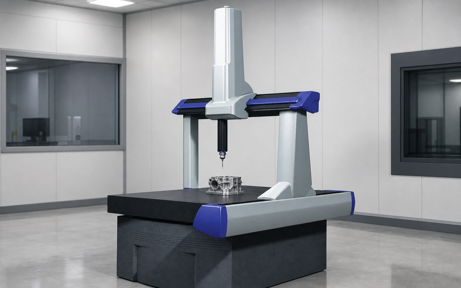
Measurement requirements are agreed before programme release. Validation plan
Define dimensional comparisons, critical characteristics and functional evidence.
Review validation - 06
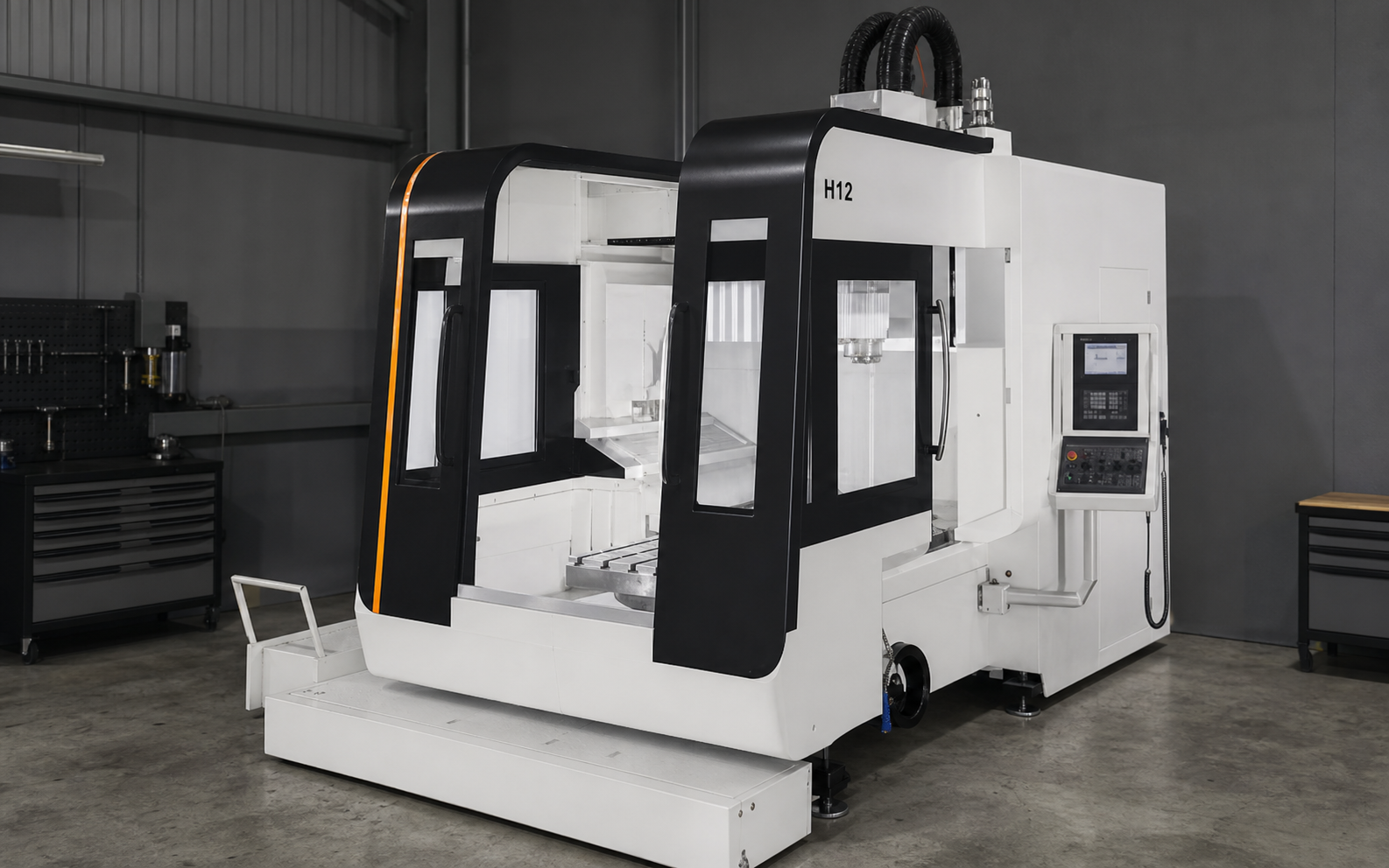
Approved product intent moves into tool manufacture through a controlled handoff. Tooling handoff
Transfer approved geometry and engineering decisions into controlled tool development.
Review tooling
Discuss your requirements
What the engineering team reviews at each gate.
| Stage | Review focus | Expected output |
|---|---|---|
| Input | Application and requirement | Agreed scope |
| Engineering | Manufacturability and process | Defined route |
| Validation | Critical characteristics | Release evidence |
| Handoff | Records and ownership | Controlled transfer |
Talk to our team
Discuss the requirement in context.
Begin with the application, material, tooling status, validation needs and programme timing.