

Blow-moulded plastic fuel tanks: define the construction and validation
We are Premier Plasmotec Private Limited, an Indian plastics manufacturer connecting engineering, tooling, moulding, completion and inspection. Our published blow-moulding page identifies HDPE fuel tanks within the hollow-component scope. A fuel-tank enquiry needs a defined construction and application; the product name alone does not establish its layer architecture or regulatory compliance.
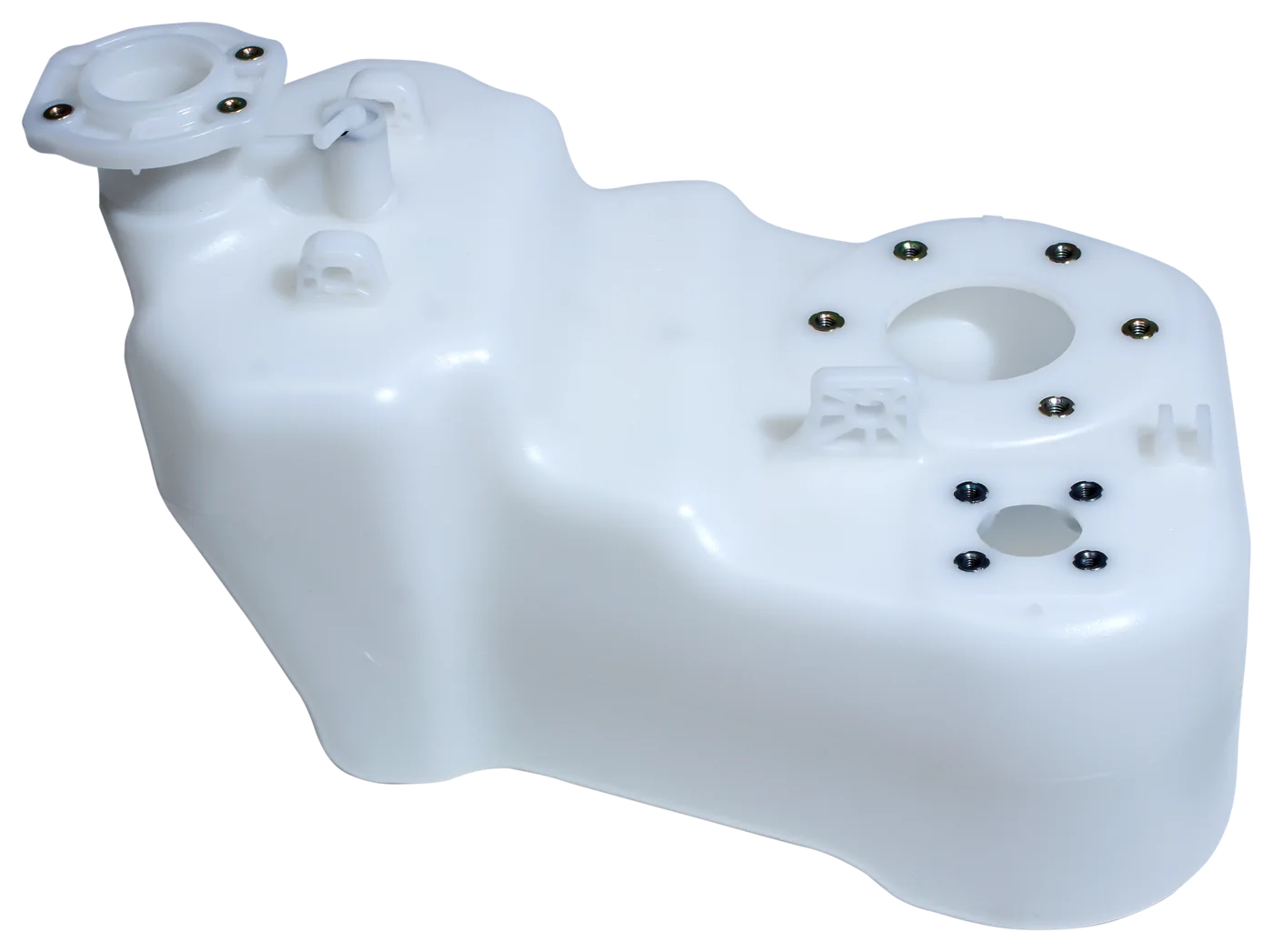
Specify the tank as part of a fuel system
Provide the fuel type, installation envelope, usable-volume definition, mounting arrangement, filler, vent and outlet interfaces. Identify any customer-supplied fittings and the responsibility for completing and testing the assembly. Include the installed orientation and nearby heat or mechanical constraints relevant to the specification.
The tank drawing should identify controlled interfaces and functional requirements as well as its shape. State the destination market and customer standard early so the engineering and validation plan addresses the intended use rather than an assumed application.
Single-layer and multilayer are separate scope decisions
Our fuel-tank scope includes HDPE components. If your programme requires a multilayer or barrier construction, specify the architecture and performance requirement so our team can assess the requested route during feasibility review.
Do not infer layer count or barrier performance from a product photograph. Keep the material specification, construction and validation record linked to the actual part revision. A proposed change in material or construction should go through the customer’s engineering and approval process.
Review wall distribution, tooling and interfaces together
Blow-moulding review should address the external geometry, wall condition, mould split and completion operations. Define where wall-related acceptance is assessed and how the component is prepared for measurement. Features that locate fittings or support the tank need attention alongside the main hollow body.
Agree the tooling ownership, trial plan, supplied items and fixture requirements. Where joining or fitting operations are part of the supply, identify the interfaces and the method of verifying completion. This keeps responsibility for the tank and its connections clear.
Use a programme-specific validation plan
The required evidence may include dimensional, leakage, exposure, permeation or mechanical requirements, depending on the application and customer specification. Identify the method, conditioning, acceptance limits and record for each applicable requirement. This page does not assert a result against an unspecified fuel-system standard.
Distinguish initial design or process validation from routine production checks. Results should identify the part, material, construction, revision and sample condition. Agree which changes require review or revalidation rather than assuming a previous result covers all future variants.
Prepare the quotation and release discussion
Send controlled part and assembly data, material and construction requirements, test specification, annual and peak demand, tooling status, packaging, target timing and destination market. State whether the supply is a bare tank or a completed assembly with fittings and inspection.
Premier’s public facility descriptions identify blow moulding at Faridabad and blow-moulded component production at Mysore. Confirm current programme allocation and usable process range against the actual tank. A dated capacity statement or a generic tank photograph is not a delivery commitment or product approval.
Continue the engineering review
Blow moulding process and hollow-part review
Discuss the part with our team
Start with the application, drawing status, material, demand and programme timing. Ask how to share confidential files.