

Premier Plasmotec Private Limited manufactures plastic components in India through connected engineering, tooling, moulding, assembly and quality teams. Our published four-wheeler portfolio includes HVAC and interior component examples. This guide explains the information needed to discuss an air duct without confusing its shape with its functional specification.
Define the duct’s job in the vehicle
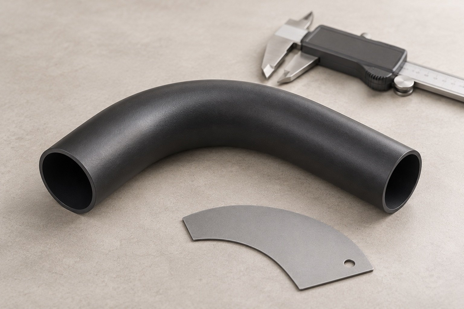
Identify the air path, inlet and outlet interfaces, installed position and adjacent parts. Explain whether the duct carries conditioned air, connects modules or distributes air to a particular region. Give the assembly model or interface drawings needed to understand its location.
An HVAC duct should not be described as an intake manifold simply because both carry air. Their functions, temperatures, pressure conditions and approval requirements may differ. State the actual system and supply boundary in the RFQ, especially when a drawing uses an internal part name that an outside supplier may not recognise.
Treat the mating interfaces as controlled features
Show connection geometry, seals, clips, fasteners and assembly direction. Identify the datums that locate the duct in the vehicle and the features that need to remain aligned after joining. Include tolerance requirements for the assembled condition where those differ from individual-part requirements.
Explain how the duct will be fitted and serviced. Assembly access, installation loads and available inspection access can affect the design. Provide the mating parts or approved interface data used for fit checks so a supplier is not trying to infer them from the duct model.
Choose the process around the geometry and requirement
Review the proposed material and manufacturing route with the engineering team. A part may need a moulded shell and joining operation or another suitable hollow-part process, depending on geometry and the specification. Do not select a route solely because the external surface can be represented in CAD.
Identify thin sections, abrupt transitions, mounting features and joining surfaces. For a hollow component, state the wall requirements and how they will be checked. The process review should explain which features are controlled by tooling and which depend on trimming, fixtures or assembly.
Specify function without inventing universal test limits
Provide the customer’s airflow, leakage, temperature, noise or mechanical requirements where applicable. Link each requirement to the test method, fixture, sample condition and acceptance limit. The relevant tests depend on the duct’s role and the vehicle programme; a generic manufacturer page cannot set those values.
If the duct is joined, define how the joining operation is checked and how the completed assembly is identified. State whether a requirement applies at initial approval, after environmental conditioning or during routine production. Record any difference between a development test and a release requirement.
Plan the tooling and assembly evidence together
Tool design should consider the mating interfaces, parting arrangement, ejection and surfaces used by assembly fixtures. When a duct consists of multiple parts, review their tolerance relationship before approving each tool independently. A set of acceptable individual pieces may still need an assembly-level check.
Premier’s published secondary-operation scope includes welding and fastening routes. Their suitability must be reviewed for the actual material and interface. Ask for the proposed process and control plan rather than assuming a named joining method suits every duct.
What the buyer should include in the enquiry
Send controlled drawings and models for the duct and mating interfaces, material specification, demand, tooling status, installed conditions, validation requirements and target timing. Identify supplied seals or fasteners, packaging needs and the exact assembly responsibility.
For a design change or transfer, add the reason for the change, existing failure information, available measurement results and tool condition. This gives the team a basis for distinguishing a tooling correction from a change in product requirement. For complete intake manifolds or fuel tanks, begin a separate review of that product’s scope and evidence rather than extending an HVAC-duct quotation by analogy.
Continue the engineering review
Hollow-component blow moulding
Injection moulding and assembly interfaces
Discuss the part with our team
Start with the application, drawing status, material, demand and programme timing. Ask how to share confidential files.