Plastic child parts for automotive intake manifolds
We are Premier Plasmotec Private Limited, an Indian plastics manufacturer connecting engineering, tooling, moulding, completion and inspection. Our public four-wheeler portfolio identifies intake-manifold child parts. We discuss tooling, manufacture and inspection for those child parts, with the supply boundary agreed against the drawing and assembly.
Define the child part and its responsibility
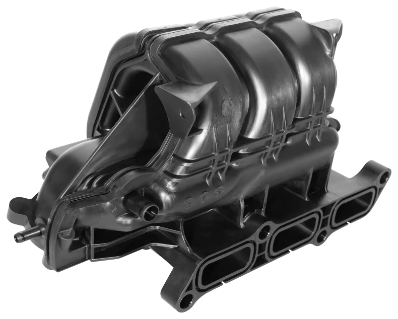
Provide the component drawing and its position in the intake assembly. Identify the parent assembly and the exact function of the supplied item. Explain whether it forms a housing feature, connection, mounting, sealing or another interface so the engineering review addresses the correct risks.
State whether the enquiry includes a loose moulding, insert, joined component or subassembly. List bought-out items and customer-supplied components and define who approves them. A part name containing manifold should not silently expand the quotation to the whole intake system.
Material and environment affect the review
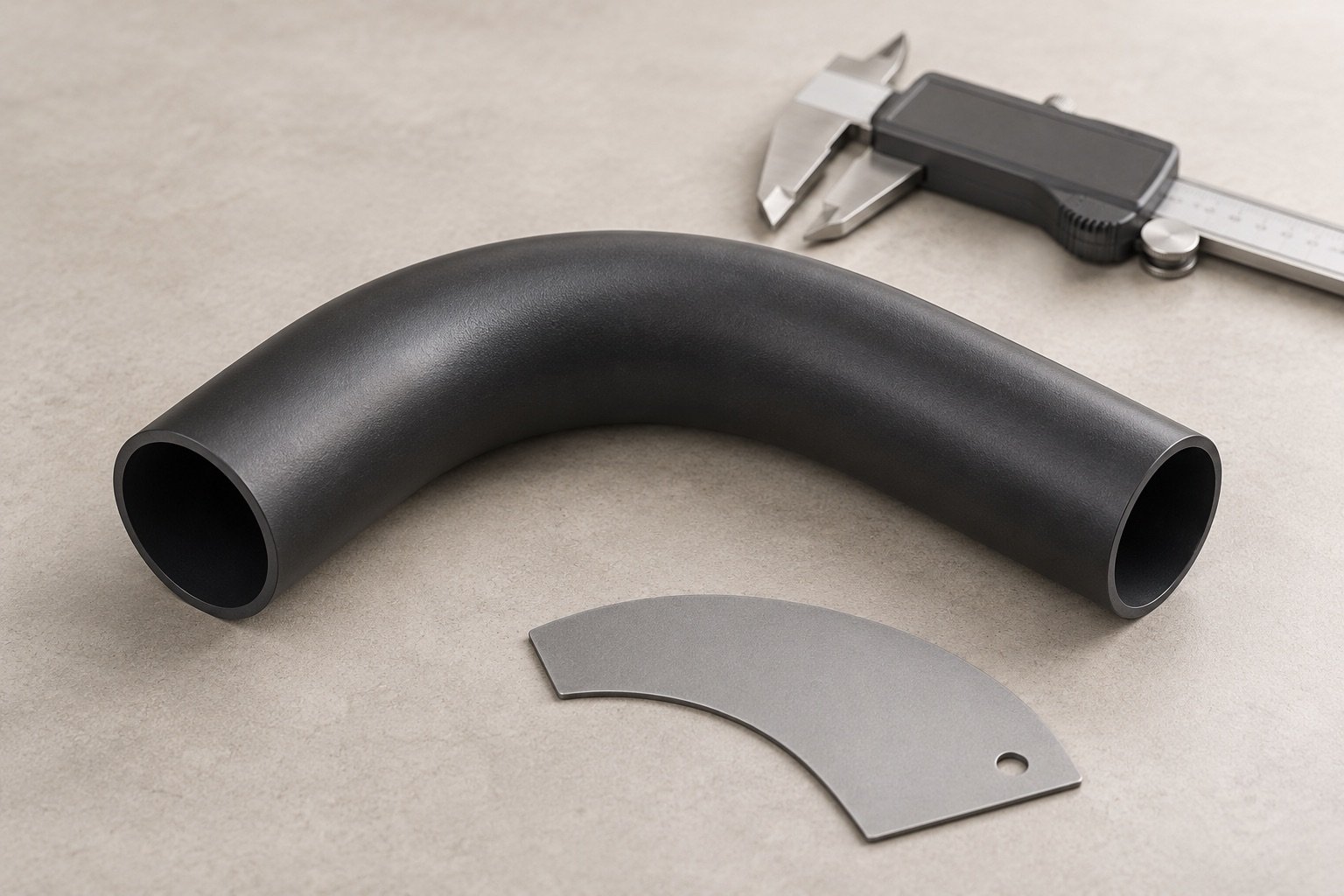
Supply the approved material grade, reinforcement and permitted alternatives. Include the relevant thermal, pressure, chemical and mechanical conditions from the customer specification. Where the customer controls design, identify who may authorise a change in geometry or material.
If these conditions are still being developed, mark them as open engineering decisions. A component supplier should not infer a complete duty cycle from a sample or a photograph. The feasibility and quotation assumptions need to remain visible until the specification is released.
Control the mating and joining features
Show datums, sealing surfaces, fastener locations, inserts and any joining interfaces. Provide the mating-part data and assembled-condition requirements needed to assess fit. Identify critical dimensions and the inspection method or fixture used to judge them.
Review these features with the tool-room and manufacturing teams before tooling is released. The parting and ejection arrangement, wall geometry and completion operations should suit the functional interfaces. For a transferred tool, include its condition, revisions and known correction history.
Validate the component within the agreed boundary
Define dimensional, appearance and functional requirements for the supplied child part. Identify any checks performed at subassembly or complete-system level and which party owns them. Component measurements do not automatically establish airflow, durability or leakage performance for a complete manifold.
Agree the sample state, test method, acceptance limits and customer submission process. Keep the evidence linked to the part revision, material and construction. Changes should follow the agreed approval and revalidation procedure.
Prepare a component-level enquiry
Send the part and assembly drawings, material specification, volume, tooling status, interface requirements, validation plan, packaging and target timing. State the exact supply boundary and any customer-owned tools or nominated bought-out items.
Our documented Indian network connects tooling, manufacturing and inspection responsibilities across programmes. Confirm the current production site and exact intake-component family with the team. A complete intake-manifold offer would require separate capability and validation evidence and is not claimed by this page.
Continue the engineering review
Moulding functional intake components
Tool and interface engineering
Discuss the part with our team
Start with the application, drawing status, material, demand and programme timing. Ask how to share confidential files.