

Blow Moulding
Hollow components. Controlled form.
Blow moulding extends the manufacturing system into HDPE fuel tanks and other hollow functional components.
Technical Scope
A controlled route for hollow functional components.
Material behaviour, wall distribution, tooling and validation are reviewed around the functional application.
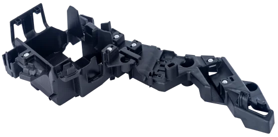
Hollow parts
Blow moulding
HDPE processing supports fuel tanks, ducts and other hollow functional component programmes.
Review manufacturing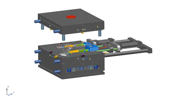
Control
Wall distribution and interfaces
Part geometry, wall distribution, split strategy and interfaces are reviewed together before release.
Review toolingEvidence
Process validation
Tool trials, dimensional checks and leak-related testing connect development to approved production.
Review validationWorking Sequence
Hollow components move through a controlled blow-moulding route.
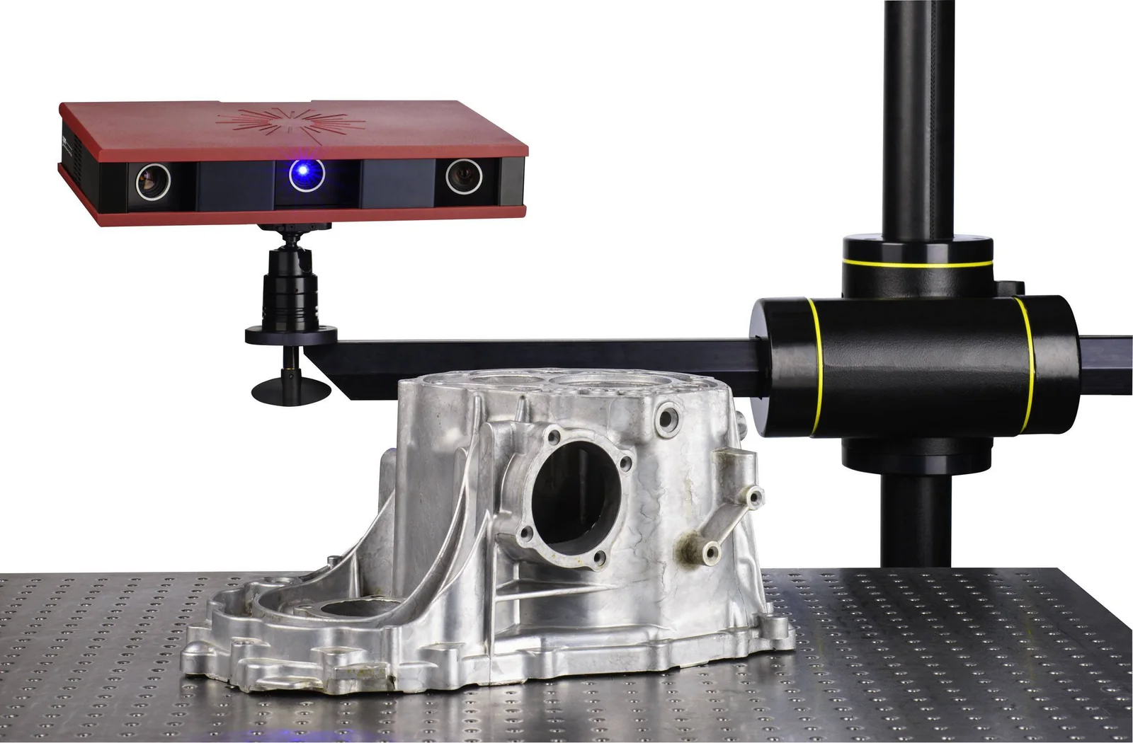
- 01
The blow-moulding route begins with geometry and functional application. Application review
Confirm the hollow-part function, envelope, material and validation requirement.
Review engineering - 02
Part and tooling decisions are resolved together before release. Part and tool definition
Review wall distribution, split strategy, interfaces and mould geometry.
Review tooling - 03
Material behaviour and moulding conditions establish the production plan. Material and process plan
Define HDPE or programme material preparation, process parameters and handling requirements.
- 04
The controlled blow-moulding cycle establishes the component shape and wall condition. Blow moulding
Run the approved process window and monitor part geometry, wall condition and interfaces.
Review manufacturing - 05
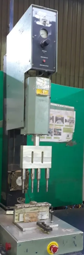
Secondary operations prepare the moulded part for validation and use. Completion
Trim, join or finish the hollow component as required by the application.
Review completion - 06
Validation and release
Review dimensional, leak-related or programme-specific functional evidence.
Review validation
Programme Review
What the engineering team reviews at each gate.
| Stage | Review focus | Expected output |
|---|---|---|
| Application | Hollow-part function, envelope and HDPE or programme material requirement | Defined component brief |
| Part and tool | Wall distribution, split strategy and interfaces | Defined moulding route |
| Process | Material preparation and controlled blow-moulding cycle | Stable hollow component |
| Validation | Dimensional, leak-related or programme-specific checks | Release evidence |
Capability Enquiry
Discuss the requirement in context.
Begin with the application, material, tooling status, validation needs and programme timing.