

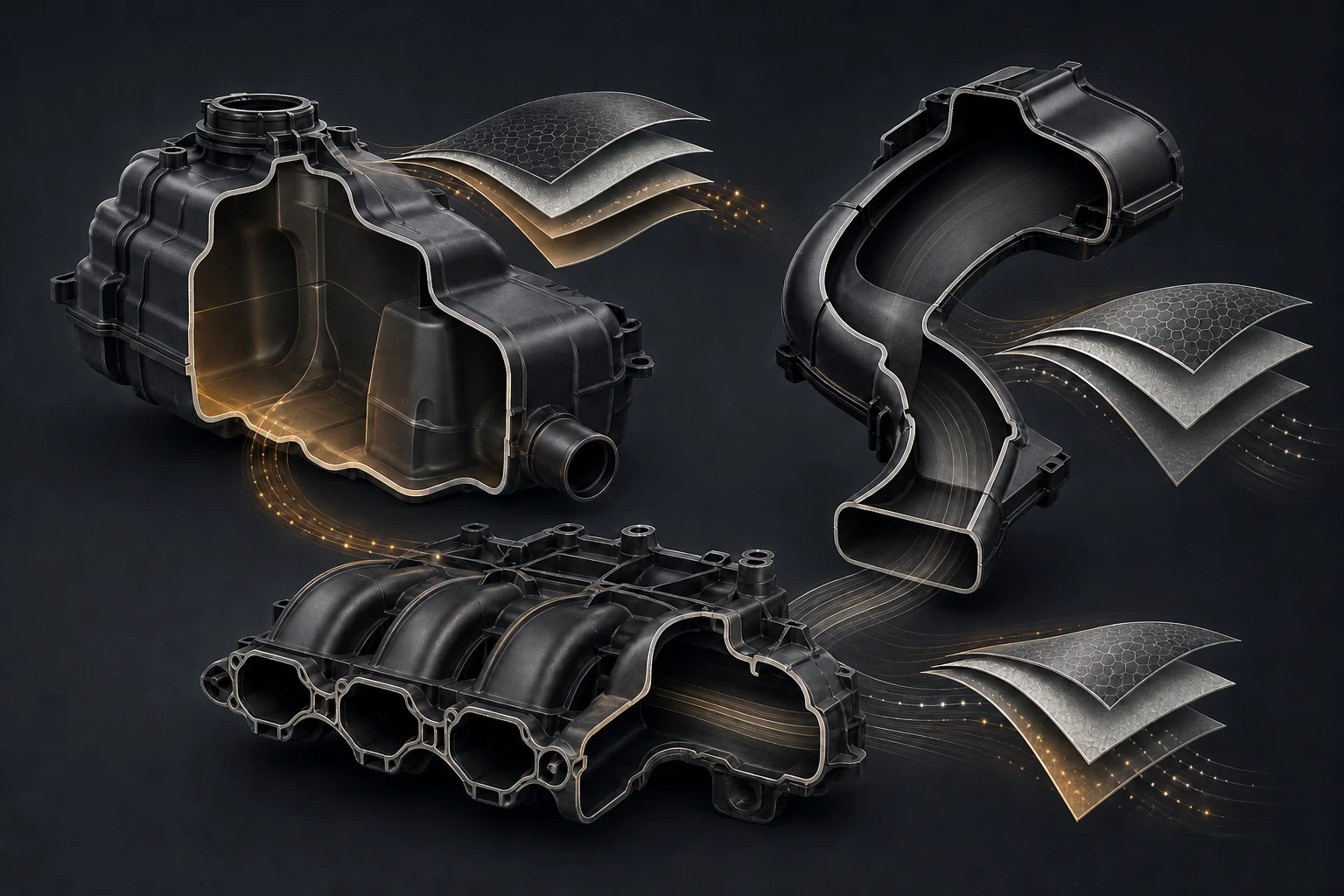
Automotive tanks, ducts and intake-system parts can look related because they all carry fluid or air, but their manufacturing routes are not interchangeable. Hollow blow-moulded parts must be separated from injection-moulded child parts and assembled systems.
For OEM procurement, product engineering and supplier-quality teams, the strongest sourcing decision comes from linking the part requirement to a practical manufacturing and validation plan. This guide explains what to specify, what to verify and what to include in the RFQ.
The essentials
- Map each component to its actual process.
- Treat material and barrier requirements as application-specific.
- Control ports, pinch-offs, welds and mating interfaces.
- Use leak, pressure, airflow or fit tests suited to the function.
Start with function, not a process label
Blow moulding is suited to selected hollow geometries formed around a parison. Injection moulding is used for many detailed child parts, flanges, clips and interfaces.
Ask the supplier to show how these requirements appear in the drawing review, process plan and inspection record. If the design is still open, agree the trial or analysis that will settle it.
Blow moulding for hollow components
An intake-manifold child part should not be described as a blow-moulded manifold without evidence. Fuel contact, vapour control and regulatory needs drive material and barrier decisions.
Compare proposals on the same input revision. A technically stronger quotation makes assumptions visible and explains what must happen before the part can be approved for serial production.
Fuel-tank architecture: single layer versus multilayer claims must be evidenced
Single-layer and multilayer constructions are distinct capabilities. A multilayer claim needs equipment, material structure and approved product evidence.
Acceptance criteria should identify the specimen condition, method, sampling plan and responsible approver. That prevents a general capability statement from being mistaken for product evidence.
What to compare
| Area | Evidence to request |
|---|---|
| Component map | Name, function and actual manufacturing route |
| Material | Fluid or air duty and any barrier requirement |
| Geometry | Wall distribution, ports, mounts and joining features |
| Completion | Welding, inserts, trimming and assembly |
| Validation | Leak, pressure, airflow, fit and durability tests |
HVAC and intake ducts: geometry, interfaces and airflow
Wall distribution in a blow-moulded part varies with geometry and process. Pinch-off regions require design and inspection attention.
This decision also affects tooling cost, trial time and long-term repeatability. Resolve it before tool release wherever possible; later correction is usually slower and more expensive.
Intake-manifold child parts and the correct injection/assembly route
Ports, necks and inserts must hold position and sealing geometry. HVAC ducts need package fit, joint retention and airflow-path control.
Ask the supplier to show how these requirements appear in the drawing review, process plan and inspection record. If the design is still open, agree the trial or analysis that will settle it.
Materials, tooling and process control
Joined parts require a defined welding or assembly process. Leak tests should state medium, pressure, stabilization, duration and limit.
Compare proposals on the same input revision. A technically stronger quotation makes assumptions visible and explains what must happen before the part can be approved for serial production.
Leak, pressure, dimensional and assembly validation
Pressure or burst tests require agreed fixtures and safety controls. Dimensional checks should focus on mounts, ports and assembly datums.
Acceptance criteria should identify the specimen condition, method, sampling plan and responsible approver. That prevents a general capability statement from being mistaken for product evidence.
Questions worth asking before nomination
- Which input assumptions could change the tool, process route or quoted price?
- Which characteristics are controlled by process settings, and which require inspection of every part or lot?
- What will be measured during trials, and who approves the result?
- How are material, cavity, machine, assembly and inspection records connected?
- What happens when a drawing, material or demand profile changes after nomination?
Material and process traceability support failure analysis and change control. The RFQ should identify function, route, interfaces, tests and demand. These questions turn a capability discussion into a clear technical and commercial responsibility map.
How Premier supports this work
Premier’s approved portfolio includes fuel-tank, duct and intake-manifold child-part evidence across the relevant component families. The manufacturing route must be confirmed part by part: hollow tanks or ducts may use blow moulding, while detailed child parts may use injection moulding and assembly.
Premier’s engineering, tooling, manufacturing and quality teams can review the requirement against the drawing, material, production volume and agreed validation plan. The useful starting point is the component data, not a generic capability question.
What to include in the RFQ
- Controlled 3D CAD and the latest drawing revision.
- Component function, mating interfaces and critical characteristics.
- Exact material grade, or the service conditions if material selection is open.
- Annual volume, peak demand, programme timing and target production location.
- Existing tooling status, target machine interfaces and ownership requirements.
- Appearance zones, packaging expectations and traceability requirements.
- Applicable customer specifications, standards and validation methods.
- Samples, mating parts and previous failure information where available.
A complete input pack shortens feasibility review and makes quotations easier to compare. If a value is not yet fixed, identify it as an open engineering decision and provide the condition it must satisfy.
Start a technical review
Send the drawing, material requirement, expected volume and validation plan through Premier’s manufacturing enquiry page. The relevant engineering, tooling, manufacturing and quality teams can then review the part and respond against the actual scope.
Related capabilities
Technical references
- Customer drawing, material specification and applicable validation standards should remain the controlling technical references.